What Is a Relief Valve and How It Protects Hydraulic Systems
A hydraulic relief valve is a safety device that opens when pressure exceeds a set limit. It prevents system damage by directing excess fluid to the tank, maintaining stable operation and protecting expensive components from failure.
- A hydraulic relief valve protects the system by opening when pressure reaches a predetermined maximum limit.
- Properly sized valves prevent damage to pumps, hoses, and cylinders without interrupting normal operation.
- Sourcing decisions should consider valve response speed, setting accuracy, and compatibility with existing pump capacities.
- Regular inspection of relief valves is necessary to ensure they open and close correctly during maintenance.
Hydraulic systems rely on controlled pressure to perform mechanical work. When that pressure exceeds safe design limits, components fail. A hydraulic relief valve is the primary defense against this condition. It acts as a pressure safety limit, opening when fluid pressure reaches a specific threshold and directing excess flow back to the reservoir.
What Does a Hydraulic Relief Valve Actually Do
A hydraulic relief valve is a pressure-operated safety device. It monitors the system pressure in the high-pressure side of the hydraulic circuit. Under normal operating conditions, the valve remains closed, allowing fluid to flow to actuators and cylinders. When pressure rises above the set point, a spring forces the spool to move. This opens a passage, allowing fluid to bypass the load and return to the tank.
The valve does not stop the pump. The pump continues to deliver fluid. The relief valve simply provides an escape route for that fluid once the set limit is reached. This distinction is critical. The pump does not build infinite pressure. The valve caps it.
How the Pressure Relief Function Works
The pressure relief function depends on the balance between fluid pressure and spring force. Most standard relief valves use a coil spring to hold the spool in the closed position. As system pressure increases, the force on the valve spool increases. When this force exceeds the spring preload, the valve opens.
There are two main types of operation. In a direct-acting valve, the spool is held by the spring alone. In a pilot-operated valve, a small pilot valve controls the main spool. Pilot-operated valves offer more precise pressure control because the pilot stage handles the fine adjustment, while the main stage handles the bulk flow.
The response time of the valve matters. A slow response allows pressure to spike briefly before the valve opens. A fast response limits the overshoot. For sensitive actuators, fast response is preferred. For general material handling, standard response times are usually sufficient.
Why System Overpressure Protection Matters
Without overpressure protection, hydraulic systems face rapid component failure. Pumps are designed with a maximum continuous pressure and a peak pressure. Exceeding the peak pressure shears gear teeth or cracks piston seals. Cylinders can burst if internal pressure exceeds the structural strength of the barrel. Hoses and fittings can fail at connection points.
Relief valves also protect the operator. A pressurized line rupture creates high-velocity fluid jets that cause severe injury. The valve reduces the likelihood of such events by capping system pressure. It is a mechanical safeguard that works regardless of operator error or sensor failure.
In system design, the relief valve setting is typically chosen based on the weakest component in the circuit. If the pump is rated for 2,100 bar and the cylinder is rated for 1,800 bar, the relief valve should be set below 1,800 bar. This ensures the cylinder is protected first.
Sourcing Decisions for Hydraulic Relief Valves
When sourcing a hydraulic relief valve, several factors influence the selection. The first is the pressure range. The valve must handle the maximum expected system pressure. The second is the flow capacity. The valve must pass the full pump flow at the set pressure without causing excessive temperature rise.
Response speed is another factor. High-speed valves are used in applications where rapid pressure transients occur, such as robotic arms or high-speed presses. Standard valves are adequate for slower, heavy-duty applications.
The type of valve also matters. Direct-acting valves are simpler and cheaper. Pilot-operated valves provide better control and are preferred for large flow systems. If the system uses multiple actuators, consider whether a single main relief valve or individual circuit reliefs are needed. Circuit reliefs protect individual branches from local overpressure.
| Valve Type | Operating Principle | Typical Application | Key Advantage |
|---|---|---|---|
| Direct-Acting | Spring-loaded spool | General industry, light duty | Simple, low cost |
| Pilot-Operating | Pilot valve controls main spool | High flow, high precision | Accurate pressure control |
| Counterbalance | Compensates for load weight | Vertical cylinders, lifting | Smooth motion, reduced energy use |
| Accumulator-Protected | Uses accumulator to absorb spikes | High impact loads | Slower response, high capacity |
A Worked Example in Plain Words
Consider a forklift hydraulic system. The pump delivers fluid to the lift cylinder and the tilt cylinder. The system design pressure is 2,000 bar. The cylinder is rated for 2,100 bar. The pump is rated for 2,500 bar.
The relief valve is set at 1,950 bar. During normal lifting, pressure fluctuates between 1,500 and 1,900 bar. The valve stays closed. The fluid lifts the load.
If the operator attempts to lift a load that is too heavy, the cylinder reaches the bottom of its stroke. The pump continues to deliver fluid. Pressure rises. At 1,950 bar, the relief valve opens. Fluid bypasses the cylinder and returns to the tank. The pressure stays at 1,950 bar. The cylinder does not burst. The pump does not overheat from building pressure. The system is safe.
If the valve were set at 2,200 bar, the cylinder would fail before the valve opened. The pump would also run hotter than designed. The setting of 1,950 bar protects the weakest component, the cylinder, while staying below the pump rating.
Maintenance and Inspection
A relief valve can fail in two ways. It can stick closed, failing to open when needed. It can stick open, allowing continuous flow to the tank. Both failures are dangerous. A stuck-closed valve leads to overpressure damage. A stuck-open valve leads to loss of pressure and system failure.
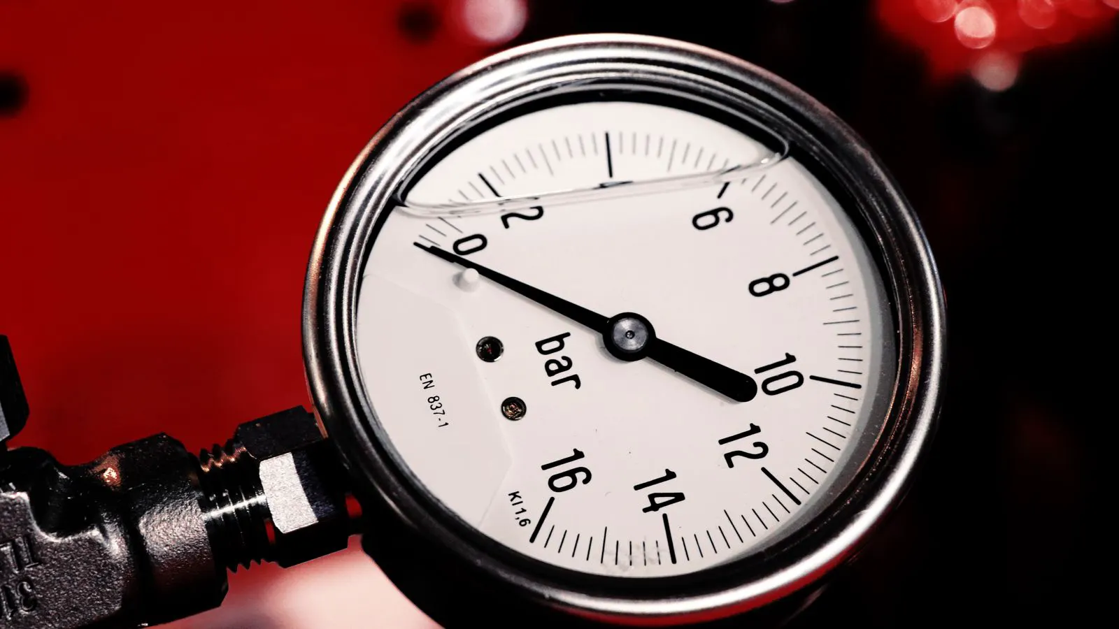
Inspection involves checking the valve setting during routine maintenance. A pressure gauge is connected to the test port. The pump is run until the gauge reads the set pressure. The valve should open at that point. If it opens early, the spring may be weak. If it opens late, the valve may be dirty or the spring may be too strong.
The return line to the tank should also be checked. A blocked return line can cause pressure buildup even if the valve is open. The tank level should be sufficient to prevent air entrainment. Low tank level causes cavitation in the pump, which can damage the relief valve spool.
Common Mistakes in Relief Valve Selection
The most common mistake is setting the relief valve based on the pump rating alone. The pump is often the strongest component. The cylinder or hose is usually weaker. The valve must be set to protect the weakest link in the circuit.
Another mistake is ignoring flow capacity. A small valve may not pass the full pump flow. This causes the valve to open partially and heat up the fluid. The system runs hot, degrading the hydraulic oil. The oil oxidizes, creating varnish that clogs the valve.
Finally, mixing valve types without understanding the interaction is a problem. Pilot-operated valves require a stable pilot pressure. If the pilot circuit is undersized, the main valve will chatter. This causes wear and inconsistent pressure. The pilot circuit must match the main valve size.
Relationship to Other System Components
The relief valve works in conjunction with the pump, filter, and accumulator. The pump provides the flow. The filter removes contaminants that can cause the valve to stick. The accumulator can absorb pressure spikes, reducing the frequency of relief valve openings.
In systems with accumulators, the relief valve setting may be adjusted. The accumulator absorbs the initial spike. The valve handles the sustained overpressure. If the accumulator is undersized, the valve opens more frequently. This increases wear on the valve spool.
The filter selection is also linked to valve health. A clogged filter raises system pressure. The relief valve sees higher pressure than intended. If the filter is bypassed or the bypass valve fails, contamination can bypass the filter. This can score the valve spool. Proper filter maintenance keeps the valve clean.
Final Thoughts
A hydraulic relief valve is not a luxury component. It is a safety device. It prevents catastrophic failure. It protects the pump, the actuators, and the operator. It maintains system stability.
When selecting a valve, look at the weakest component in the circuit. Match the flow capacity to the pump. Choose the response speed for the application. Verify the setting during maintenance. A well-chosen and well-maintained relief valve extends the life of the entire hydraulic system. It is the first line of defense against overpressure. It is simple in principle. It is critical in practice.
Frequently asked questions
What happens if a hydraulic relief valve fails to open?
The system pressure continues to rise until a component fails. This can damage the pump, cylinder, or hose, and may cause a dangerous fluid leak.
Can a relief valve be adjusted to a lower pressure?
Yes, most valves have a spring preload that can be adjusted. Lowering the setting protects more sensitive components but may reduce system performance if set too low.
What is the difference between a relief valve and a pressure regulator?
A relief valve protects against maximum pressure limits. A pressure regulator maintains a specific operating pressure level. The relief valve is a safety device; the regulator is a control device.
How often should a hydraulic relief valve be tested?
Testing should be part of the regular maintenance schedule. At minimum, the setting should be verified during annual inspections or after any major component replacement.
Does the type of hydraulic oil affect relief valve performance?
Viscosity and cleanliness affect valve response. High viscosity can slow the spool movement. Low cleanliness can cause sticking. Use the oil recommended for the system to ensure proper valve function.