Diagnosing Low Hydraulic Pressure: Step-by-Step Isolation Guide
Low hydraulic pressure usually traces to pump wear, relief valve faults, or internal leakage. This guide isolates the root cause through sequential pressure testing and component inspection to prevent unnecessary repairs.
- Start at the gauge and work backward to the reservoir to isolate the fault.
- Check relief valve settings before replacing expensive pump components.
- Monitor temperature and fluid condition to distinguish between thermal issues and mechanical wear.
- Record baseline readings during normal operation for faster future diagnosis.
- Isolate suspect components one at a time to avoid false positives.
A pressure gauge reading below specification triggers immediate concern. Operators may feel the load is heavy, the machine may move slowly, or actuators may stall under load. Low hydraulic pressure rarely appears without a clear mechanical or fluid dynamic cause. This guide walks through the isolation sequence engineers use to locate the fault without guessing.
Confirm the Gauge and Reading First
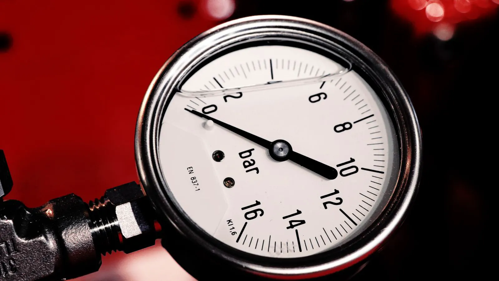
Before touching any hydraulic component, verify that the measurement itself is valid. A faulty pressure gauge or blocked gauge line gives a false low reading. Remove the gauge, inspect the capillary tube for debris, and compare it against a known accurate reference gauge. If the reading matches, proceed. If not, replace the gauge or the line. This step sounds basic but eliminates a large share of reported pressure faults that never had a mechanical cause.
Gauge failures often stem from mechanical shock or vibration. A cracked diaphragm or a broken pointer shaft can create a reading that appears stable but is physically wrong. The capillary tube connecting the gauge to the system port is prone to blockage. Metal shavings from a worn pump or dried varnish from the fluid can settle in the narrow tube, restricting fluid flow to the gauge face. This restriction creates a pressure drop that the gauge registers as low system pressure.
Check the gauge installation for cross-threading. If the fitting is not tight, air ingress can occur, especially when the system pressure fluctuates. Air bubbles in the capillary line compress and expand with system pressure changes, causing the needle to flutter or drift. Ensure the gauge face is oriented correctly. If the gauge is installed upside down, the fluid in the case can pool around the mechanism, causing friction and erratic movement. Replace the gauge if the reference test shows a discrepancy greater than one percent of the full scale range.
Check Reservoir Level and Fluid Condition
Open the reservoir sight glass or dip tube. A low fluid level means the pump is cavitating, which drops pressure and generates noise. Top up with the correct fluid type and viscosity for the operating temperature. While you are at the reservoir, pull a fluid sample. Dark, milky, or gritty fluid signals oxidation, water contamination, or particulate damage. Water in the fluid compresses, reducing effective pressure. Particulates abrade pump clearances and valve seats. If the fluid is dirty, the filter history usually explains why. A clogged return filter or a bypassed main filter can both cause pressure loss. Replace filters per schedule and check for bypass valve wear.
Low reservoir levels are often the result of slow leaks or insufficient top-ups. Inspect the reservoir for weeping around the filler neck seal or the sight glass gasket. Even a small leak that runs slowly can drop the level over several days. A pump drawing air from a low reservoir creates cavitation. The air bubbles collapse inside the pump case, causing internal pitting and a distinct growling or whining sound. This damage accelerates wear on pistons, gears, and bearings.
Fluid condition is a direct indicator of system health. A fluid sample taken from the reservoir should be clear and free of visible particles. Milky fluid indicates water contamination, which can result from condensation in the tank or a failed cooler seal. Water reduces the lubricating properties of the fluid and causes corrosion. Gritty fluid contains solid particles that act as abrasives. These particles scratch the bore of the pump and the spools of the control valves. Dark fluid suggests oxidation. Oxidation occurs when the fluid is exposed to high temperatures and oxygen for extended periods. It creates varnish that clogs small orifices and valves.
Check the filter bypass indicator. If the filter is clogged, the bypass valve opens to protect the pump. This allows unfiltered fluid to circulate, introducing dirt into the system. A bypassed filter can also restrict flow, causing a pressure drop that mimics a pump fault. Inspect the filter element for damage. A torn element releases fine metal shavings into the system. Replace the element and flush the filter housing before installing a new one.
Isolate the Pump Section
Connect a pressure gauge directly to the pump discharge port, upstream of the control valve and actuator lines. With the engine at rated speed, run the system under a known load.
- Record pressure at no load and at rated load.
- Compare the reading against the pump nameplate maximum pressure.
- Listen for a growling or whining sound that indicates cavitation.
- Check suction line restriction and strainer condition.
Testing the pump in isolation removes downstream variables. By measuring pressure at the pump outlet, you determine if the pump is generating the required force. If the pressure at the discharge port is low, the pump is the source of the problem. If the pressure at the discharge port is normal but the pressure at the actuator is low, the issue lies in the lines, valves, or actuators.
Pump faults vary by type. Gear pumps are robust but have limited tolerance for wear. As the gear teeth wear, the clearance between the gears increases, causing internal leakage. This leakage reduces the efficiency of the pump and lowers the maximum pressure it can sustain. The noise profile changes as well. A healthy gear pump runs quietly. A worn gear pump produces a distinct whining sound that increases with load.
Piston pumps are more sensitive to fluid viscosity and alignment. A slight misalignment between the pump and the drive motor can cause internal friction and heat. This heat degrades the fluid and accelerates seal failure. If the pump reads correctly at no load but drops under load, it often indicates internal leakage past the pistons or the check valves. This is not a field repair. The pump needs bench testing or replacement. Bench testing involves measuring the pump efficiency and pressure drop across the pump body. The test results will identify the specific component that is failing.
Test the Relief Valve
The pressure relief valve is the most common source of low pressure that is not a pump failure. With the system at operating temperature, slowly reduce the relief valve setting while monitoring the gauge. If pressure follows the setting down, the valve is working correctly. If pressure stays below the set value, the valve is stuck open, the spring is fatigued, or debris is preventing the poppet from seating.
The relief valve protects the system by opening when the pressure exceeds a set limit. If the valve is stuck partially open, it allows pressure to bleed back to the reservoir continuously. This creates a permanent pressure loss. The valve may appear closed visually, but the poppet or spool may not be seating fully against the valve seat.
Clean the valve body and inspect the spool and spring. A small piece of varnished metal or filter paper can wedge the valve open. Varnish is a sticky residue formed from oxidized fluid. It adheres to metal surfaces and prevents smooth movement. Soak the valve parts in a suitable degreaser and clean them thoroughly. Inspect the spring for fatigue or corrosion. A fatigued spring will not provide the correct force to close the valve. Replace it if the spring is distorted or if the tension is low.
Reinstall the valve and reset it to specification. Do not over-tighten the adjustment. Exceeding the rated pressure can damage the pump and hoses. The relief valve setting should match the maximum operating pressure of the weakest component in the system. If the setting is too high, the system will overpressure. If it is too low, the system will not reach its operating pressure. After cleaning and resetting, run the system and verify that the pressure stabilizes at the new setting.
Inspect Hoses, Lines, and Fittings
Pressure loss in the lines is less common than pump or valve faults but does happen. Look for bulges, kinks, or crushed sections in hoses. Check fittings for weeping or internal bypass. A cracked hose that holds pressure at low flow can leak internally under high flow. Isolate sections by disconnecting lines and testing the pressure drop across each run. If a section drops pressure significantly, replace it. Use proper flare or compression fittings and torque to spec. Cross-threaded fittings are a classic hidden leak.
Hydraulic hoses are subjected to constant pressure and vibration. Over time, the inner liner can degrade, allowing fluid to seep into the braid. This internal leak is not visible from the outside but causes a pressure drop. A hose that has been kinked or bent sharply can have a collapsed section. This restriction increases the pressure drop across the hose. Replace any hose that shows signs of damage, bulging, or abrasion.
Fittings are a common source of leakage. Check each fitting for weeping. A weep that is not visible at low pressure may become a leak at high flow. Use a clean cloth to wipe each fitting. If the cloth becomes wet, the fitting is leaking. Cross-threaded fittings are difficult to detect. The thread engagement is shallow, creating a leak path. Remove the fitting, clean the threads, and re-torque it to the specified value. Use thread sealant or a seal ring as recommended by the manufacturer.
Check Actuator and Control Valve Leakage
If pump pressure is normal but pressure at the actuator is low, the loss is downstream. Test each cylinder or motor individually. Disconnect the load, run the pump, and measure pressure at the actuator port. A cylinder that leaks internally shows low return pressure and slow movement. A directional control valve with worn spool seals will bleed pressure back to the tank.
Actuators convert fluid pressure into mechanical force. Internal leakage in a cylinder reduces the force output. The cylinder may move slowly or stall under load. Test each cylinder individually by isolating it from the system. Measure the pressure at the cylinder port while the pump runs. A healthy cylinder should maintain pressure without significant flow. If the pressure drops or the flow is high, the cylinder is leaking internally.
Directional control valves are prone to spool wear. The spool moves within the valve body and is sealed by O-rings or seals. As these seals wear, fluid leaks from the high-pressure port to the low-pressure port or to the tank. This leakage reduces the pressure available to the actuator. Test the valve by applying pressure to one port and measuring the pressure at the other. A healthy valve should maintain pressure with minimal flow. If the pressure drops, the valve is leaking internally.
Run a flow test and compare it to the pump rated flow at the same pressure. If flow is normal but pressure is low, the actuator or valve is leaking. If both are low, the pump or upstream restriction is the cause. Internal leakage in a cylinder often starts with the rod seal, then moves to the head seal, then to the piston. Replace seals in sets. Mixing old and new seals accelerates wear. The rod seal is exposed to the environment and wears first. The head seal is exposed to the reservoir fluid and wears second. The piston seal is internal and wears last.
Review Temperature and System Design
A system that runs hot will show lower pressure than a cold system. Hydraulic fluid viscosity drops with temperature. A pump sized for 40 degrees Celsius may not hold pressure at 70 degrees. Check the cooling loop, heat exchanger, and ambient conditions. If the system is designed for high ambient temperatures, the reservoir may need a larger volume or a second cooler. Do not blame the pump for a thermal issue. Record the operating temperature with the pressure reading. A pressure drop that tracks temperature is a design or cooling fault, not a component failure.
Hydraulic fluid viscosity is a critical factor in system performance. As the temperature increases, the fluid becomes thinner. This reduces the lubricating film between moving parts and increases internal leakage. It also reduces the pump efficiency. A system that operates at high ambient temperatures may overheat. The heat exchanger may be insufficient to remove the heat generated by the system.
Check the cooling loop for blockages. Dust and debris can clog the heat exchanger fins. Clean the fins regularly to ensure proper airflow or water flow. Check the ambient temperature and record it with the pressure reading. If the pressure drop correlates with the temperature rise, the system is thermally overloaded. A system that runs hot will show lower pressure than a cold system. A pump sized for 40 degrees Celsius may not hold pressure at 70 degrees. The reservoir may need a larger volume to absorb the heat or a second cooler to remove the excess heat. Do not blame the pump for a thermal issue.
Pressure Loss Diagnosis Summary
The table below summarizes the most common symptoms, likely causes, and corrective actions. Use it as a quick reference during field troubleshooting.
| Symptom | Likely cause | What to do |
|---|---|---|
| Low pressure at all gauge points | Pump internal wear or cavitation | Test pump discharge, check suction, replace pump if needed |
| Pressure low only under load | Relief valve stuck open or pump leakage | Clean and retest relief valve, bench test pump |
| Low pressure at actuator only | Cylinder or control valve internal leak | Isolate actuator, test for return pressure, replace seals |
| Pressure fluctuates with temperature | Fluid viscosity drop or thermal design issue | Check cooler, verify fluid spec, review system capacity |
| Pressure drops after long idle | Air in system or seal bypass | Bleed air, inspect and replace worn seals |
| Normal flow but low pressure | Internal bypass in valve or pump | Flow test at pressure, isolate components, replace faulty part |
Prevention and Baseline Records
Keep a log of pressure readings at normal operating conditions. Record the date, temperature, load, and gauge location. This baseline makes future diagnosis faster. A pressure drop of five percent over a month is a trend, not an event. Watch for it. Inspect hoses and fittings during scheduled maintenance. Replace seals before they fail. Use the correct fluid and keep the reservoir clean. A system that is maintained predictably rarely shows mysterious low pressure. When it does, the isolation steps above point to the root cause quickly and accurately.
Establishing a baseline is a proactive measure. Record the pressure readings under standard operating conditions. Include the date, temperature, load, and gauge location. This data provides a reference point for future comparisons. A small pressure drop over time may indicate wear or contamination. A sudden drop indicates a failure. By tracking the readings, you can identify trends before they become failures.
Inspect hoses and fittings during scheduled maintenance. Look for signs of wear, damage, or leakage. Replace seals before they fail. Use the correct fluid and keep the reservoir clean. A system that is maintained predictably rarely shows mysterious low pressure. When it does, the isolation steps above point to the root cause quickly and accurately. Regular maintenance extends the life of the hydraulic system and reduces downtime.
Frequently asked questions
Can a clogged filter cause low hydraulic pressure?
Yes. A clogged suction filter restricts flow to the pump, causing cavitation and pressure loss. A clogged return filter can raise system pressure but reduce effective actuator pressure. Check both.
How do I tell if the relief valve is the problem?
Reduce the relief valve setting slowly and watch the gauge. If pressure follows the setting, the valve is functional. If pressure stays low regardless of setting, the valve is stuck open or internally damaged.
Should I replace the pump first or the relief valve?
Test the pump discharge pressure before replacing anything. If the pump reads low at its outlet, the pump is the fault. If pump pressure is normal but system pressure is low, the relief valve or downstream components are the likely cause.
What fluid conditions cause low pressure?
Water contamination, incorrect viscosity, and degraded oil all reduce effective pressure. Water compresses and causes spongy operation. Low viscosity at high temperature reduces pump output. Replace fluid and clean the reservoir.
How often should I check hydraulic pressure?
Check during start-up and at rated load during scheduled maintenance. Record the reading each time. A trend over several checks is more useful than a single reading.